Cooling🔗
Fittings🔗
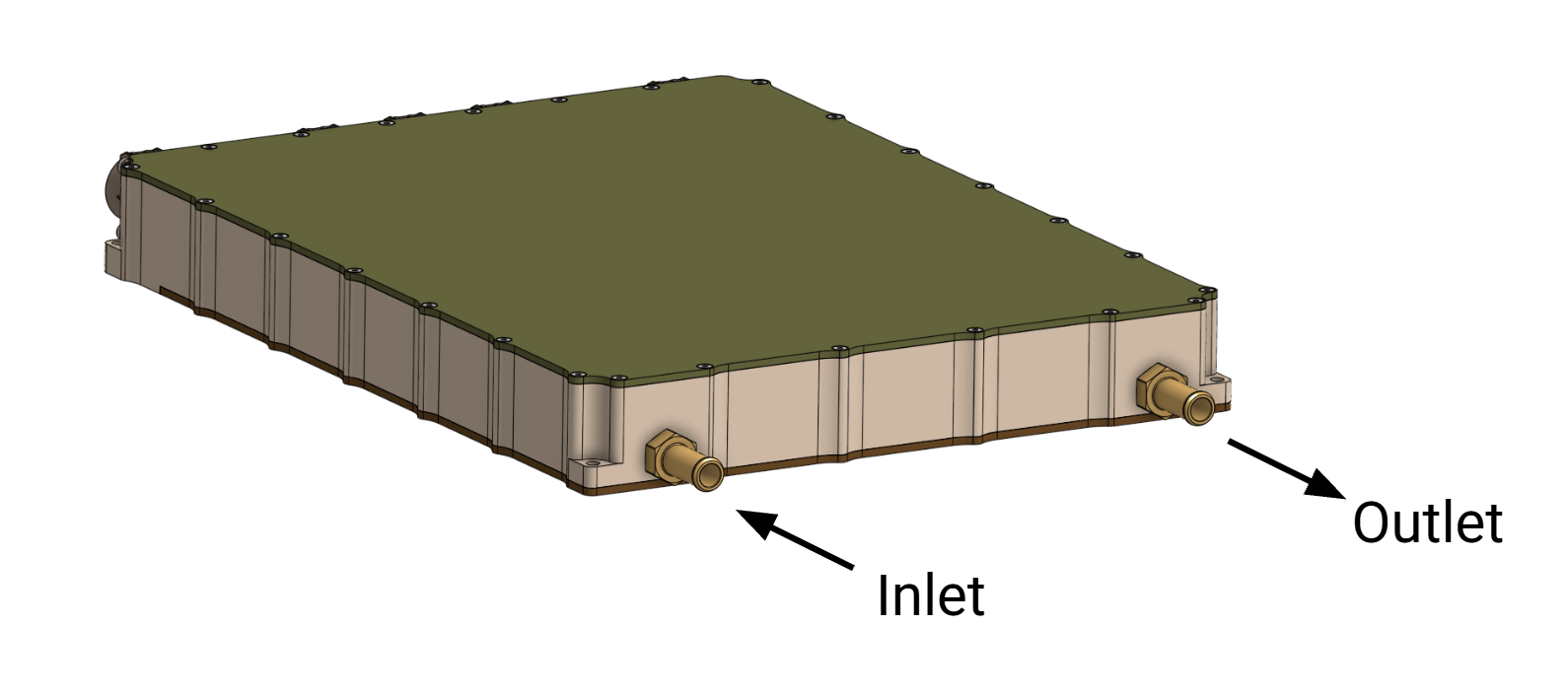
Two coolant ports are fitted to the rear of the MC0-500 enclosure. These ports are used for motor controller cooling under normal operation.
The coolant ports and cooling geometry are symmetric and coolant flow is allowable in either direction.
However, due to internal heating characteristics it is recommended that when viewed from the rear, the left port is used as the inlet, and right port as the outlet.
As-provided, MC0-500 ships with two straight 1/2” barbed tube fittings (Deatschwerks 6-02-0503). This is meant to be used with a flexible hose with an ID of 1/2”.
When selecting tubing, ensure that it is rated for the expected coolant pressure at elevated coolant temperatures during normal operation.
The stock fittings can be replaced with any 6AN ORB male threaded fittings. Use care when tightening fittings, it is easy to overtighten the threads. It is recommended to first fully hand tighten, then use a 19mm wrench to tighten an additional quarter turn. Do not use any thread sealant or lubricant.
It is recommended to use only plastic or aluminum-based components within the MC0-500’s loop. Mixing of other metals can cause galvanic corrosion.
Coolant🔗
The coolant plate is rated for a maximum inlet pressure of 3.1 bar (45 psi) relative to ambient. Pressures in excess of the maximum may cause leakage of coolant and degraded performance.
Coolant consisting of a commercially available 50/50 mix of water and glycol is required for operation. Do not use plain water as this will cause corrosion. The maximum recommended inlet temperature is 60C at full load operation.
Flow Requirements🔗
The recommended flow rate to MC0-500 is 25 LPM. This corresponds to a pressure drop across the inverter of about 1 bar (15psi).
The maximum junction temperature of the internal FETs is 150C. At full load, the temperature delta between the inlet temperature and maximum junction is approximately 90C.
The pressure drop to flow rate relation of the MC0-500 coldplate is:
