Connectors🔗
The front face of MC0-500 has all of the device’s connectors. When facing the front of the device, the connectors are, from left to right:
HV Minus
LV Connector
PHC
PHB
PHA
HV Positive
Name |
Location |
Connector |
|---|---|---|
DC + |
Front left |
Amphenol PL00X-301 |
Phase C |
Centre left |
Amphenol PL00X-301 |
Phase B |
Centre |
Amphenol PL00X-301 |
Phase A |
Centre right |
Amphenol PL00X-301 |
DC - |
Front right |
Amphenol PL00X-301 |
Low Voltage IO |
Front left |
Hirose F13WBRB-20SD |
The I/O ports are as follows:
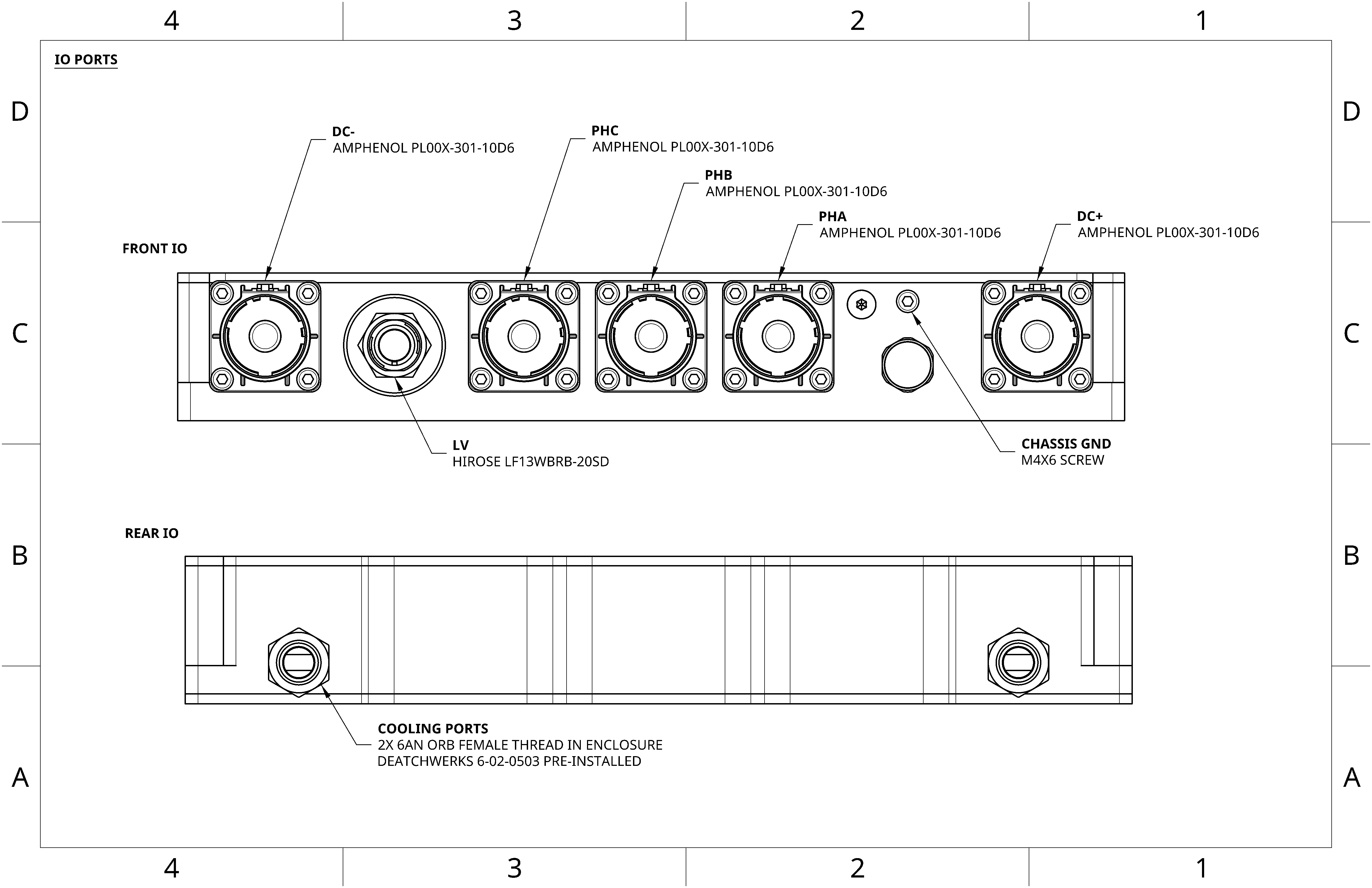
All connectors on MC0-500 have an IP67 seal or better when mated with manufacturer-specified mating parts and properly sized wiring.
LV Connector🔗
The LV connector on MC0-500 is the LF13WBRB-20SD from HIROSE. When mated, this connector achieves an IPX7/IPX8 rating. The mating part is either LF13WBP-20P or LF13WBLP-20P; both come in crimp and solder varieties and support shielding. The provided harness follows the diagram below, which also includes pinout information for the LV connector. Refer to the HIROSE documentation for additional information.
The pinout is as follows. The wire color and twisted pair group columns refer to the included shielded pigtail harness.
LV Connector Pinout🔗
Pin |
Signal |
Description |
Wire Color (included harness) |
Twisted Pair Group (included harness) |
|---|---|---|---|---|
1 |
+LV_IN |
Main LV supply input |
Red |
Red / Blue |
2 |
CAN_L |
CAN Low |
Green |
Yellow / Green |
3 |
CAN_H |
CAN High |
Yellow |
Yellow / Green |
4 |
EXT_GPIO_0 |
External GPIO |
Purple |
Black / Purple |
5 |
EXT_GPIO_1 |
External GPIO |
White |
White / Pink |
6 |
GND |
Ground |
Blue |
Red / Blue |
7 |
GND |
Ground |
Black |
Black / Purple |
8 |
ETHERNET_N |
100BASE-T1 Automotive Ethernet - |
Brown |
Brown / Gray |
9 |
RESOLVER_COS_P / ENCODER_A_P |
Resolver COS+ / Encoder A+ |
Pink-Gray |
Pink-Gray / Blue-Red |
10 |
EXT_RTD_P |
External RTD Positive |
White-Green |
White-Green / Green-Brown |
11 |
EXT_GPIO_2 |
External GPIO |
Pink |
White / Pink |
12 |
RESOLVER_SIN_N / ENCODER_B_N |
Resolver SIN- / Encoder B- |
Pink-White |
Pink-Brown / Pink-White |
13 |
ETHERNET_P |
100BASE-T1 Automotive Ethernet + |
Gray |
Brown / Gray |
14 |
RESOLVER_SIN_P / ENCODER_B_P |
Resolver SIN+ / Encoder B+ |
Pink-Brown |
Pink-Brown / Pink-White |
15 |
RESOLVER_EXC_P / ENCODER_Z_P |
Resolver Excitation+ / Encoder Z+ |
White-Gray |
White-Gray / Gray-Brown |
16 |
EXT_RTD_N |
External RTD Negative |
Green-Brown |
White-Green / Green-Brown |
17 |
RESOLVER_COS_N / ENCODER_A_N |
Resolver COS- / Encoder A- |
Blue-Red |
Pink-Gray / Blue-Red |
18 |
+LV_IN |
Main LV supply input |
White-Yellow |
White-Yellow / Brown-Yellow |
19 |
ENCODER_POWER |
Encoder supply (5V) |
Brown-Yellow |
White-Yellow / Brown-Yellow |
20 |
RESOLVER_EXC_N / ENCODER_Z_N |
Resolver Excitation- / Encoder Z- |
Gray-Brown |
White-Gray / Gray-Brown |
The LV input supports 11 V to 52 V operation on +LV_IN.
HV Connectors🔗
Warning
If the correct OD wire is not used with the mated connector, the IP67 rating will not be achieved. Pay close attention to the required wire diameter when sourcing the harness.
MC0-500 has five high-voltage connectors, all of which are PL00X-301 connectors from Amphenol Industrial. Each has its HVIL (High Voltage Interlock) daisy-chained internally, and a fault is detected if any connector is improperly seated.
To run MC0-500 at its maximum rated current, the mating part should be crimped with 70 mm2 or larger wire. When mated, this connector achieves an IP67 seal.
The mating parts are PL18X-301, PL28X-301, PL10X-301, and PL20X-301.
Grounding🔗
An M4x0.7x6 socket head cap screw is provided on the front of the enclosure, located above the pressure vent.
Provide a continuous low impedance connection between MC0-500’s grounding point, chassis ground, and the motor’s ground.