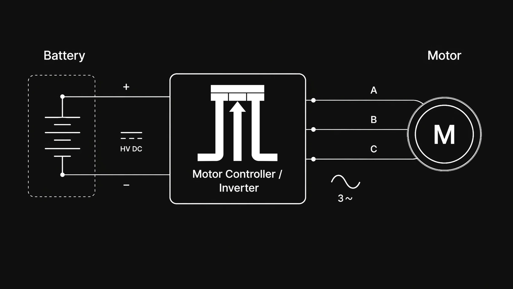
One of the most painful signs of poor power electronics design is that single-tone, high-pitched whine. Everyone has heard it before: you plug in some electronic device and it rings. This sound is usually called coil whine: the magnetic parts of a converter (inductors, transformers, motor windings) physically vibrating at the frequency of the current ripple. It's jarring, it's unnatural; humans are used to broadband noise. We're not built to be exposed to this extreme concentration of narrowband sound.
You can hear it in all forms of switching power electronics: EVs, PC PSUs, phone chargers, DC-DCs, AC-DCs, DC-ACs, TVs.
Some engineers accept this sound as an inevitability: you're switching transistors at high frequency, so there's going to be a hum. This is a myth, and it's used by lazy engineers to accept poor designs.
In the modern era, we have wide-bandgap (WBG) devices that allow us to switch extremely efficiently. The switching device is almost never the bottleneck in modern power electronics; it's systems design.[1] In effectively all situations, if you're switching at a frequency that enters the audible range, you're doing something very wrong.
Where Coil Whine Comes From
The whine we hear from switching power electronics is due to a few select system parameters.
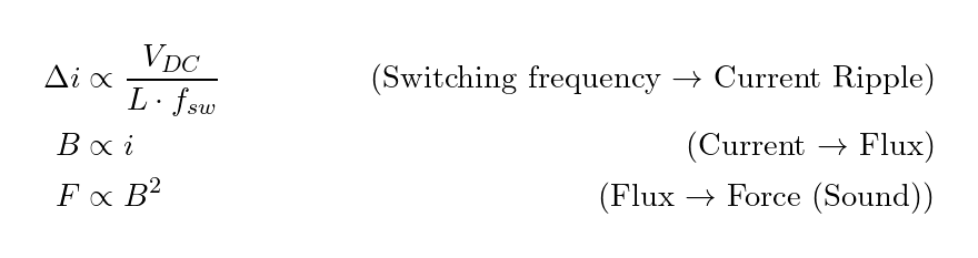
Switching Frequency → Current Ripple
The switching frequency of your power electronics system sets the current ripple. We get current ripple because our switches apply a square-wave voltage to some inductor. When we apply a voltage across an inductor, we get a changing current. In most power electronics applications we want a continuous, smooth waveform, but our switches can only sit ON or OFF; the faster we switch them, the smoother the waveform is.
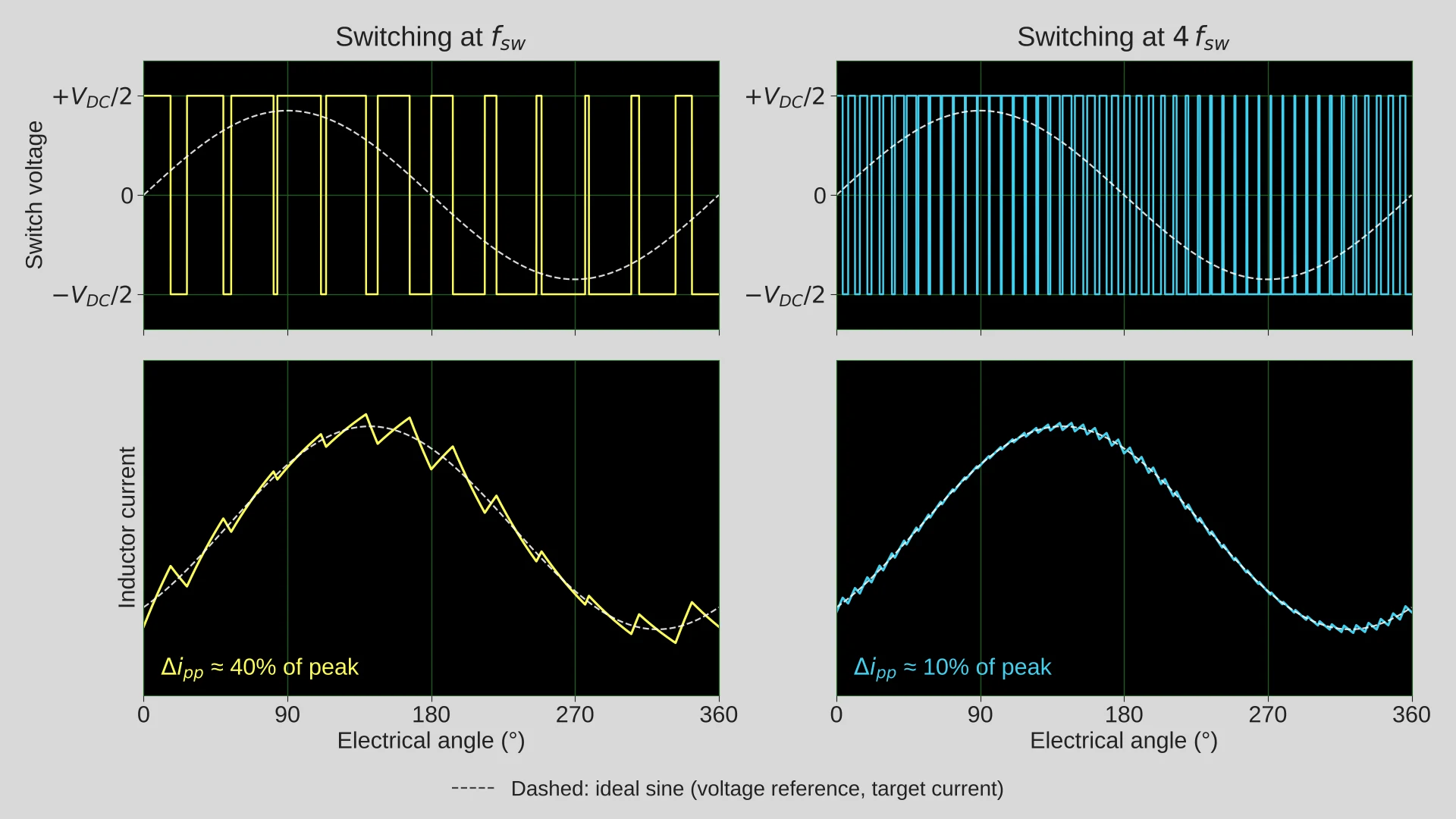
Increasing switching frequency has some tradeoffs, though, and doing it right significantly increases the complexity of most designs. So most designers switch slowly and deal with the painful consequences.
Current Ripple → Flux
When we have current ripple, we have some component of current that is not useful. In a motor, we can think of this as sinusoidal current that is outside of our electrical frequency (some harmonic); it's an oscillating current that does little to no useful work.
This current passing through some inductance induces a magnetic flux, as shown by Ampère's circuital law:
Flux → Force → Sound
We now have some changing magnetic field, and this changing magnetic field/flux density exerts mechanical stress on the inductor, described by the Maxwell stress tensor:
Effectively, our inductor is acting like an electromagnet being driven by the current ripple. This fast mechanical oscillation displaces the air and generates sound energy that we hear.
Cores add a second mechanism: magnetostriction. Ferrite and electrical steel physically change length when magnetized, so the core itself vibrates with the ripple flux, and in many inductors and transformers this is louder than the Maxwell forces.
Human Audible Range and Frequency Selection
The upper limit of human hearing is ~20 kHz.[2] This declines with age; as we get older, it drops to between 12 and 14 kHz.
What this means is that when we hear this high-pitched coil whine, we're hearing radiated noise below 20 kHz, likely below 18 kHz. We typically hear a single high-pitched tone because most of the current ripple in a switching converter happens at . This implies that the switching converter is switching at <9 kHz.
Measured: 8 kHz 2-Level vs 31.25 kHz 3-Level
To demonstrate the acoustic effect of switching frequency, I took our Steinmetz 31.25 kHz 3-level inverter and benchmarked the audio emissions of a motor setup against a standard 8 kHz 2-level inverter.
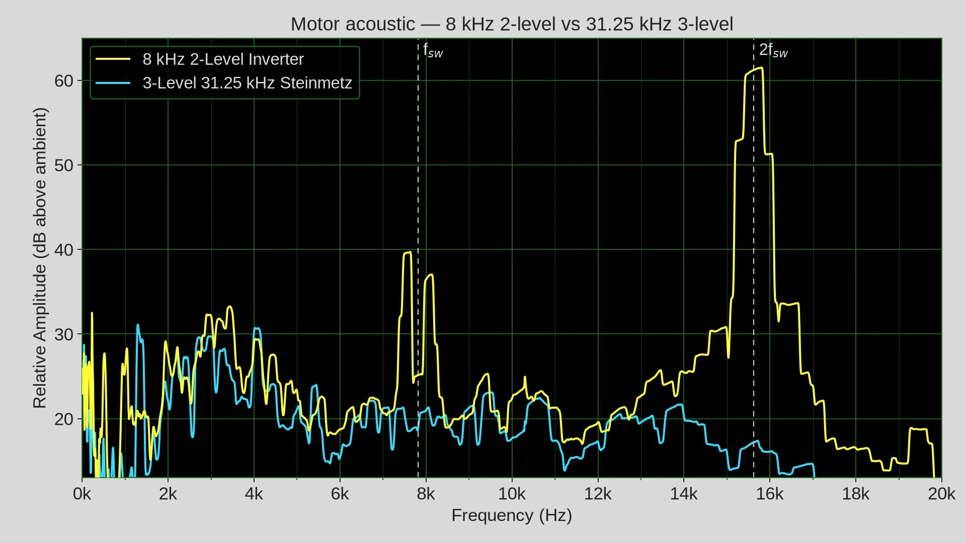
| 8 kHz 2-Level | 31.25 kHz 3-Level (Steinmetz) | |
|---|---|---|
| Switching frequency | 8 kHz | 31.25 kHz |
| Peak at fsw ~8 kHz (dB above ambient) | 40 dB | 20 dB |
| Peak at 2fsw ~16 kHz (dB above ambient) | 63 dB | 15 dB |
| Dominant tone in audible band | 16 kHz | N/A |
You can see in the plot above that the Steinmetz inverter has an effectively flat audio distribution; it's broadband audio. The sound is effectively just the rotation of the motor and some structural resonances in the dynamometer (dyno/test stand).
With the 2-level inverter, we see sharp peaks. We see two lobes around . These come from the PWM carrier being modulated by the motor's electrical frequency : the switching harmonics aren't pure tones at multiples of , they're split into sidebands at .[3] In a three-phase inverter, the component exactly at is common to all three phases and cancels line-to-line, so the energy lands in the sidebands on either side of it. That's the dip you see right at between the two lobes, and it's the usual signature of PWM-induced magnetic noise in motors.[4] But the dominant peak is at .
The reason we don't see any peaks on the Steinmetz audio trace is that the switching frequency is 31.25 kHz, which is already above the audible band. The significant harmonic would be at 62.5 kHz, >3× the upper limit of human hearing. Additionally, the Steinmetz inverter is multilevel, which means the current ripple is dramatically reduced, as each switching cycle only has to switch a fraction of the voltage.
What Ripple Costs Beyond Noise
Rotor Magnet Heating
Motors suffer pretty significantly from current ripple.
A significant challenge in motor design is cooling the rotor magnets. Cooling the stator is easy because, per its name, it's stationary: you can pass cooling channels around the coils to suck heat out of them. Cooling the rotor is challenging because it's spinning; typically, designers try to have it conduction-cooled by the motor housing.
Current ripple in a motor induces eddy currents in the rotor magnets. These eddy currents heat up the rotor magnets, which, as stated before, suffer from poor cooling. When the rotor magnets heat up enough, they begin to demagnetize, and you can completely demagnetize and brick your motor.
Low-Inductance Motors
The trend in modern motor design is toward low-inductance systems. Low-inductance motors are exciting from a motor-design perspective, as they allow low torque ripple, fast current response, and fewer turns. Axial-flux designs tend to have lower inductance due to their larger air gap.
Low-inductance motors, however, yield a higher ripple current at a given switching frequency. Many new motors cannot be used with older inverters, as those inverters cannot switch and regulate at the switching frequency required to maintain a sine wave with low enough THD. Eventually, your sine wave becomes so distorted with ripple that regulation is impossible.
Losses, Packaging, and Cost
Overall, higher switching frequencies tend to yield lower overall loss, smaller packaging, more efficient operation, and an overall cheaper device. There's a misconception that switching frequencies are capped to maintain low loss. In the vast majority of products this is false; they're capped due to a failure of design and effort.
Higher switching frequencies allow smaller, lower-loss passives, typically lower overall current per switching device, and smaller filtering components.
In our experience, most American hardware companies accept power electronics devices 3× bigger than the frontier.
Takeaway
If you are ever looking to level up your power electronics, don't hesitate to reach out to sales@steinmetzmotors.com or owen@steinmetzmotors.com. Don't accept the mediocrity of existing COTS devices. It's time to push the frontier; the world is many orders of magnitude from the physical limit of power electronics.
References
- J. W. Kolar, D. Bortis, and D. Neumayr, "The ideal switch is not enough," in Proc. 28th Int. Symp. Power Semiconductor Devices and ICs (ISPSD), Prague, Czech Republic, Jun. 2016, pp. 15–22. PDF
- A. Rodríguez Valiente, A. Trinidad, J. R. García Berrocal, C. Górriz, and R. Ramírez Camacho, "Extended high-frequency (9–20 kHz) audiometry reference thresholds in 645 healthy subjects," Int. J. Audiology, vol. 53, pp. 531–545, 2014. doi:10.3109/14992027.2014.893375
- D. G. Holmes and T. A. Lipo, Pulse Width Modulation for Power Converters: Principles and Practice. Hoboken, NJ, USA: Wiley-IEEE Press, 2003.
- J. Le Besnerais, V. Lanfranchi, M. Hecquet, and P. Brochet, "Characterization and reduction of audible magnetic noise due to PWM supply in induction machines," IEEE Trans. Ind. Electron., vol. 57, no. 4, pp. 1288–1295, Apr. 2010. doi:10.1109/TIE.2009.2029529