
To understand the purpose and function of a motor controller, it's important to understand how an EV (electric vehicle) system works.
Structure of EV (Electric Vehicle) Systems
As shown in the figure below, there are three main parts of a standard EV system: the battery, the motor controller, and the motor.
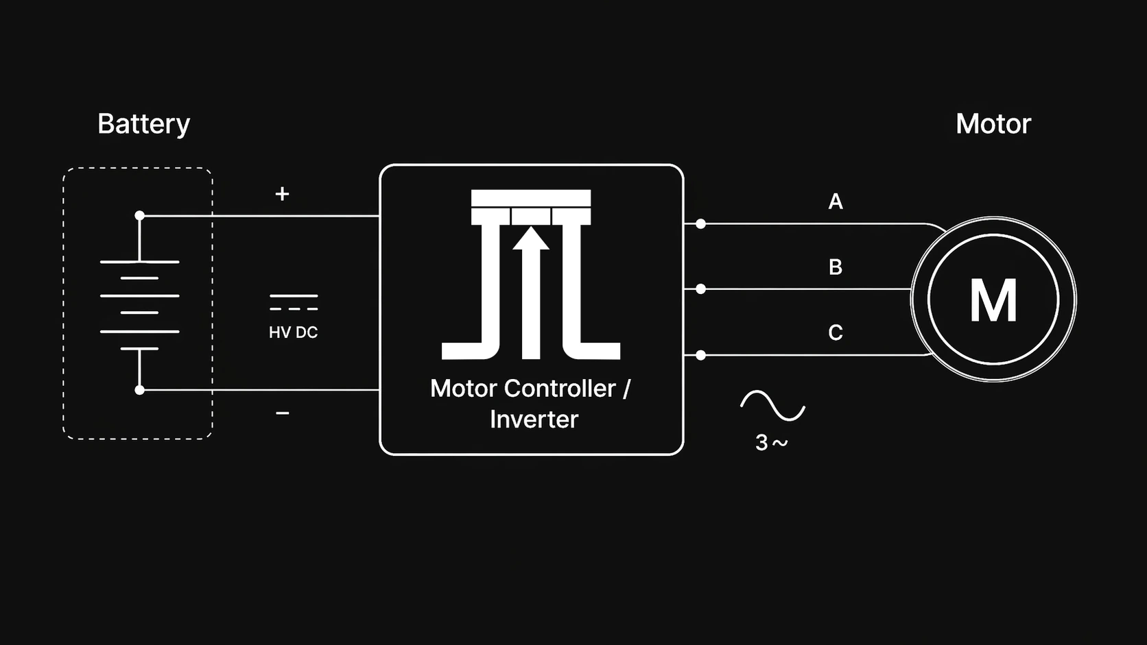
Battery
The battery is a collection of stacked cells placed in series and parallel to create the desired voltage, current capability, and capacity. The battery is the storage component of the system and outputs DC voltage and supplies current to the motor controller.
| System | DC Bus Voltage |
|---|---|
| Legacy robotics/drones | 12V |
| Modern robotics/drones | 48V |
| Legacy EVs | 300–450V |
| Modern EVs + aerospace | 800V |
Motor Controller
At a high level, the motor controller is a conversion device that takes in DC power and converts it into AC power to drive the motor.
Motor
The motor is the device that converts electrical energy into mechanical rotational energy.
There are a few types of motors, but for the sake of analysis, we'll focus on PMSMs/BLDCs as they are the most common in high-performance applications.
| Motors compatible with a three-phase motor controller | Motors that need a different controller topology |
|---|---|
| PMSM/IPMSM/SPMSM | Brushed DC |
| SynRM | Stepper |
| BLDC | SRM |
| Induction |
Each of the compatible motors will have three-phase connections. These phase connections carry alternating current (AC). Each AC motor has a different mechanism of action to convert AC current into rotational energy.
The concise explanation is as follows.
- Current flowing through a wire creates a magnetic field (Ampère’s law / Biot–Savart law)
- When you wrap the wire into a coil, those magnetic fields add together and the coil behaves like an electromagnet with controllable strength and polarity
- If you drive multiple coils with alternating currents that are phase-shifted in time, they create a magnetic field that rotates around the motor
- The rotor experiences torque and turns as it tries to align with that rotating magnetic field (Lorentz force)
What does a Motor Controller / Inverter do?
As stated above, a motor controller performs DC-to-AC conversion, converting power from the battery into power for the motor. This seems like a very simple task, but the engineering and technology that goes into doing this in a lightweight, compact, and efficient package is incredibly complex.
Motor Controller vs Inverter
First, let’s deal with these two terms: motor controller vs inverter. They are used roughly interchangeably in industry. Tesla has a Drive Inverter team. Others call it a traction inverter. In lower-power systems, people often say “motor controller”. Both terms have their quirks.
A "motor controller" refers to any device that controls the actuation of an electric motor. It's generic and certainly applies to three-phase traction inverters, but could also be applied to Brushed DC motor controllers.
An inverter is a device that performs "inversion": converting DC electrical power into AC electrical power. Thus it is a more specific term when referring to the technology but broader in application (e.g. solar inverters, battery inverters, VFDs, etc.)
I prefer the term motor controller. It is less specific to the technology, but less pretentious and provides a more intuitive understanding of the device without relying on technical jargon.
How a Motor Controller generates an AC Waveform
Creating an AC waveform from a DC bus from first principles is simple. If you have a DC+, DC- and a phase output terminal, you switch the phase terminal between DC+ and DC− very quickly. The raw phase voltage is still a pulse train, but by changing the pulse widths, the average voltage follows a sinusoidal pattern. The motor winding inductance smooths that into a much more sinusoidal current.
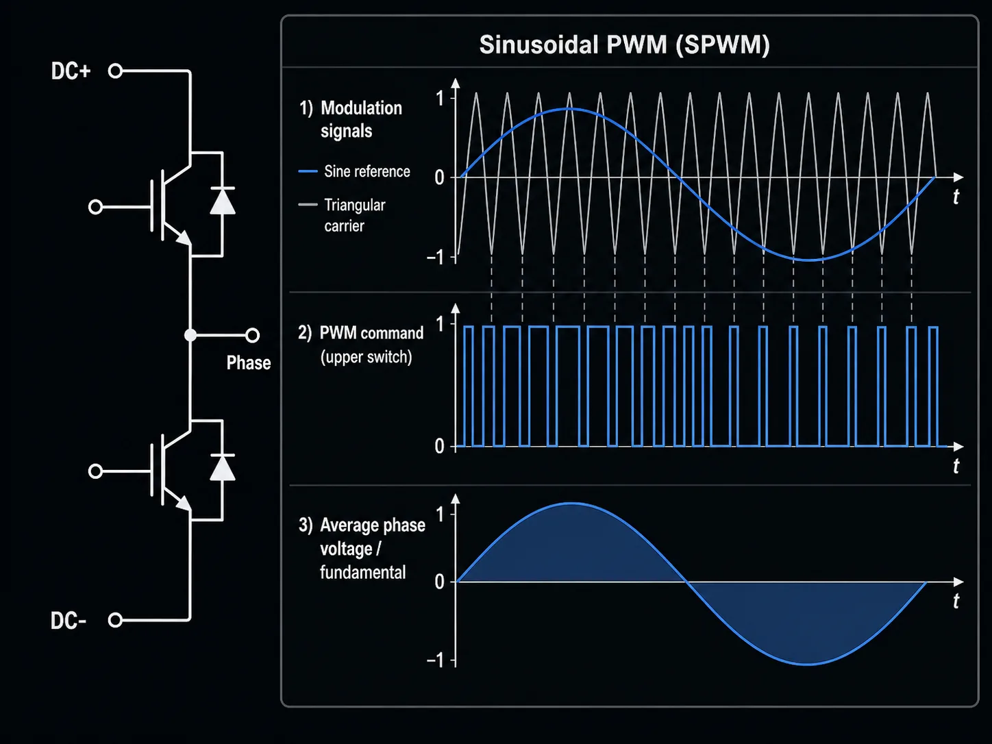
The figure shows how switching the transistors in a "half-bridge" can produce a pulse pattern whose average follows a sine wave. The voltage pulses at the phase output get "averaged" out by the inductance in the motor.
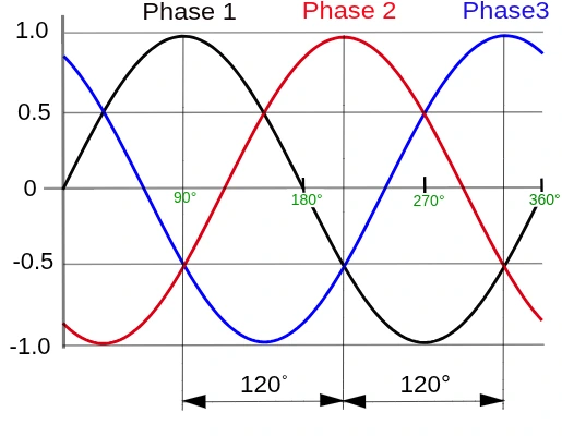
The motor controller has 3 of these "half-bridges" to be able to produce 3 different AC current waveforms. The AC current waveforms are all the same frequency and amplitude but differ in phase offset by 120 degrees as shown below.
How to Spin a Motor?
Given that we understand how to generate an AC waveform for a motor, the question becomes how do we use the AC waveform to cause a motor to spin.
To spin an AC motor you need to control the frequency, phase and amplitude of your current waveform to get the desired response from the motor. One common way to generate the switching commands is called Space Vector PWM. Most motor control methods require some heavy math and linear algebra which is out of scope for this article.
Frequency
The electrical frequency sets the speed of the rotating magnetic field. Mechanical speed then depends on motor pole count, and for induction motors also on slip. The equation below describes the relationship between the motor's speed and the electrical frequency of the current waveform for an AC motor.
Amplitude
The amplitude of the current waveform broadly determines the torque of the motor. The equation below demonstrates how increasing the amplitude of the current waveform yields higher torque. More current = more torque.
Phase
To properly drive an AC motor, you have to phase-align the current waveform with the electrical position of the rotor. This alignment has to be maintained so the motor produces consistent torque. With perfect alignment, all the current applied to the motor is converted into mechanical torque.
If the current vector is aligned correctly, most of the current goes into torque-producing current. If it is intentionally shifted, some current goes into the flux-producing axis instead. In field weakening, the controller applies negative d-axis current to reduce effective motor flux, trading some torque for more speed above the normal voltage limit.
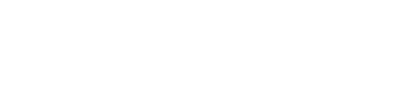
Motor Controller Architecture
A motor controller can be broken down into 3 key components:
- Sensors (Input)
- Controls (Intermediate)
- Power Stage (Output)
Sensors (Input)
A motor controller can contain a large number of sensors (or, using clever control techniques, very few), but the most typical ones are:
Current Sensing: 2 or 3 current sensors to measure the different phase currents used for torque / current control. This can include: shunts, hall-effects, TMRs, Rogowski coils, etc.
Position Sensing: A method to determine the mechanical rotation of a motor. This is used to determine the relative phase of the motor so the switching angle can drive the correct sine wave. This can be: a resolver, incremental encoder, sin/cos encoder, etc.
Voltage Sensing: Often DC bus voltage sensing is included, this can be helpful for the motor controller in performing sensorless control, more accurate torque control, protect against faults, etc.
Temperature Sensing: Typically the temperature of both the motor and transistors inside the inverter are measured to protect against damage.
Controls (Intermediate)
Inside practically every motor controller is some sort of MCU (microcontroller unit). This MCU processes the sensor signals and applies them through some complex algorithms to produce the PWM outputs that drive the power stage.
The motor controller will typically have a standard method of communication with external devices, so the rest of the vehicle can send torque or speed commands to drive the motor controller. Typical communication methods are: CAN, Automotive Ethernet (100Base-T1) and LIN (rare). The microcontroller will factor in these inputs to configure the motor controller and adjust the desired output.
Power Stage (Output)
The power stage is the core of the inverter design. It consists of:
Transistor Half-Bridges: The collection of transistors that perform the switching to generate the sinusoidal outputs. There are a wide variety of transistor technologies designers use, each with different tradeoffs including: Si MOSFETs, SiC MOSFETs, IGBTs, BJTs, GaN HEMTs, etc.
DC-Link Capacitor: This is a key component that will be discussed in great detail in later articles. The DC-link capacitor helps stabilize the DC bus, it prevents dips and ripple on the DC voltage bus from transient current spikes due to the switching of the half-bridges.
Cooling: Different motor controller power levels require different cooling topologies. Typically for anything >10kW a motor controller must be liquid cooled otherwise the volume/mass/cost of the device becomes exorbitant. For lower power motor controllers small finned heat sinks are often used.
Takeaway
A motor controller is not just a box you place near a motor. It is a critical and complex aspect of the electric vehicle drivetrain.
The hardware has to switch high voltage and high current efficiently. The software has to keep the motor synchronized, regulate current, handle faults, and communicate with the rest of the vehicle. The mechanical design has to move heat out fast enough for the whole thing to survive.
Motor controller design and selection is a daunting task, and many engineers get it wrong. I'll cover proper selection in a future article. But it's critical to understand at a fundamental level what each piece of your vehicle is doing to ensure proper optimization as well as assist in debugging.
If you're applying these concepts to a high-voltage vehicle or machine program, compare Steinmetz's 1000V motor-controller lineup, review the MC0-500 technical documentation, or send your voltage, motor, cooling, packaging, and volume requirements for an application-fit review.